
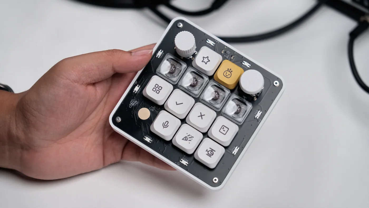
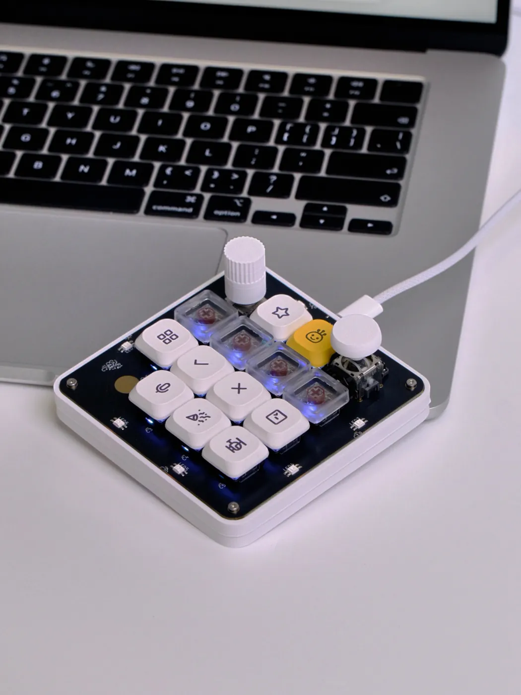
In July 2026, OpenAI shipped its first branded hardware: the Codex Micro, a $230 macropad built with Work Louder. Thirteen keys, a dial, a joystick, a touch sensor, RGB lighting, Bluetooth, and a CNC aluminium and polycarbonate case.
OpenMicroKbd is an open-source board that recreates that control layout. MIT licensed, wired USB-C, and about $37 in parts and assembly for one board. The schematic, firmware, companion app, routed board, and the full manufacturing package are all published — you can send the Gerbers to a fab today.
This is an independent open-source project, not affiliated with, endorsed by, or sponsored by OpenAI. "Codex Micro" refers to OpenAI's product; all trademarks belong to their respective owners. I will not sell OpenMicroKbd — the point is that you can make it without me.
Project snapshot
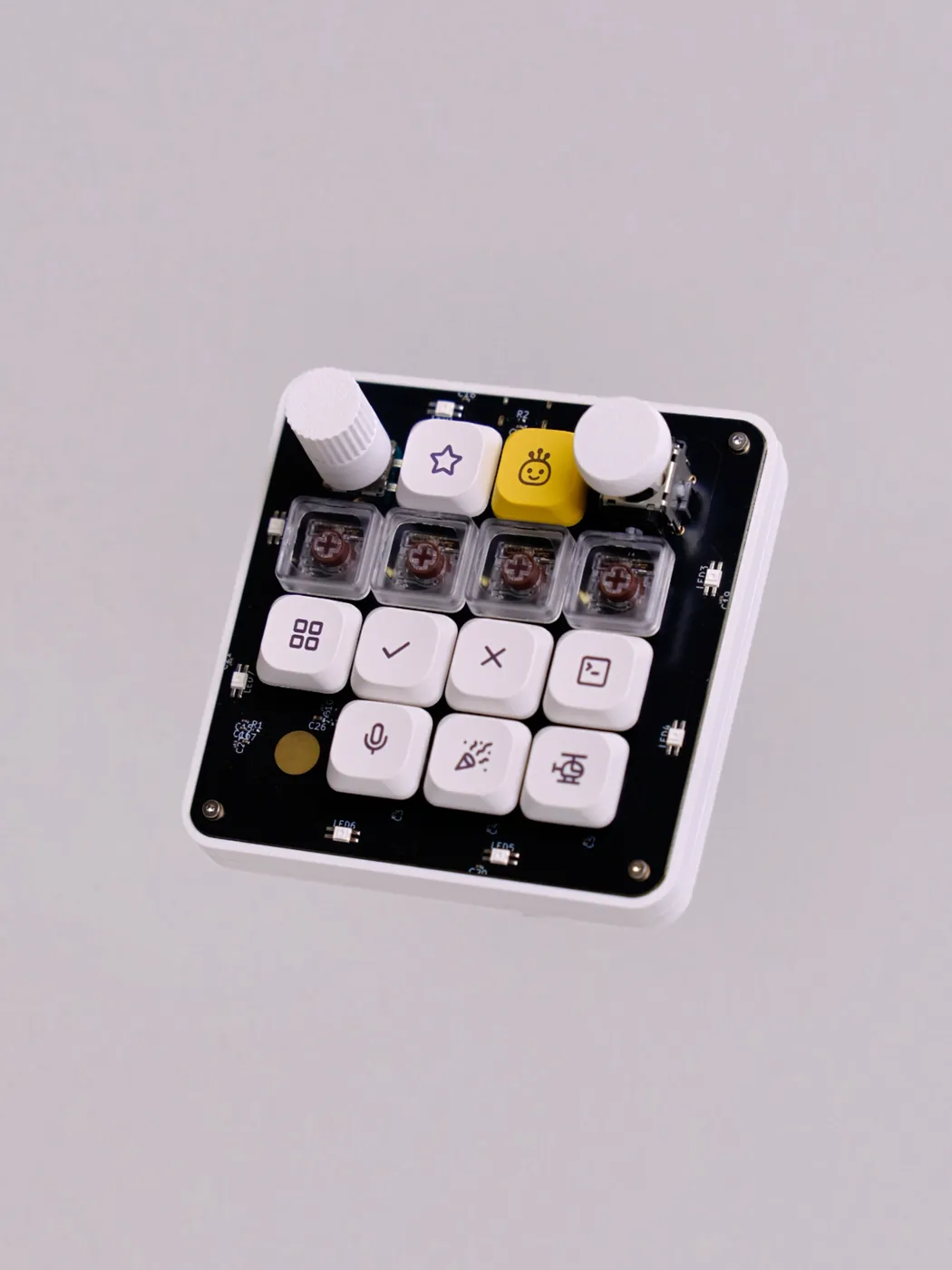
- Device — wired USB-C macropad: 13 low-profile switches, an encoder, a joystick, a capacitive touch pad, 21 addressable LEDs
- Cost — about $37 for one assembled board (PCB + turnkey SMT + switches + keycaps, one-off prototype pricing)
- Stack —
STM32F072· Rust + Embassy firmware · Rust + GPUI desktop app · MIT - Repository — github.com/conol-ai/openmicrokbd
- Published — CoHDL schematic source, generated netlist / BOM / footprints, the routed
openmicro.kicad_pcb, a fab-ready Gerber package, firmware, and the host app - Not a substitute for — the commercial device's wireless operation, its battery, or its machined case
It began as a recreation of the Codex Micro's layout, but it is not limited to Codex. It targets AI-assisted coding, terminal workflows, video editing, color grading, and other work built around shortcuts and scrubbing.
Every input's emitted code is configurable and stored in the board's own flash. Out of the box the keys send F13–F20 and Shift+F13–F17 — deliberately chosen because those are interceptable on every OS and collide with nothing — but you can reassign any key to a different keycode, a modifier-qualified combination, or a media usage, save it to the device, and it keeps that mapping on any machine you plug it into.
Why build one at all
The Codex Micro is genuinely interesting hardware. Its six frosted Agent Keys display thread state: idle, thinking, complete, needs human, error.
That status integration is tied to the ChatGPT desktop app, which bridges thread state to the LEDs. Use Codex CLI, a browser, VS Code, or JetBrains and those six keys go static or dark. There is no public device SDK.
Reactions converged on that mismatch. Ars Technica asked why OpenAI's first branded hardware was a light-up keyboard. The New Stack asked whether anyone needed one. TechCrunch called it fun for some coders and mystifying to others. An HN reader put the engineering objection more bluntly: "This is just a Macropad, right? All of the smarts are on the PC side. So why is it so expensive?"
Price is the hook, but it is not really the argument.
The problem worth solving is not that the macropad costs $230. It is that a general-purpose input device keeps its most interesting behavior behind one application.
So the goal here was a board with the same physical vocabulary and none of that boundary: open schematic, open firmware, open host app, and a manufacturing package anyone can send to a fab.
There was a second motive, and it is the reason this particular board exists rather than some easier one. I have been building CoHDL, a hardware description language for PCBs, and I needed to prove it on something real with awkward requirements: a key matrix, a rotary encoder, an analog joystick, a capacitive touch pad, two LED chains, and a USB power budget to respect. Small enough to finish. Complicated enough to be a fair test.
A complete device here has four layers — PCB, enclosure, firmware, host application — and the sections below follow that boundary.
Part one: a PCB complicated enough to be useful
The board uses an STM32F072CBT6 Cortex-M0 with 128 KiB of flash and 16 KiB of SRAM. It includes an 8 MHz HSE crystal and a 2×3 SWD debug socket. It measures 95 × 95 mm on a 4-layer stackup: signal, two ground planes, signal.
Controls occupy a square 4×4 grid at 19.05 mm spacing:
- 13 Kailh Choc V2 switches, each with a
1N4148Wdiode — thirteen independent 1U positions - An
EC11encoder with push - An
RKJXVanalog joystick with push - A capacitive touch electrode implemented directly as PCB copper
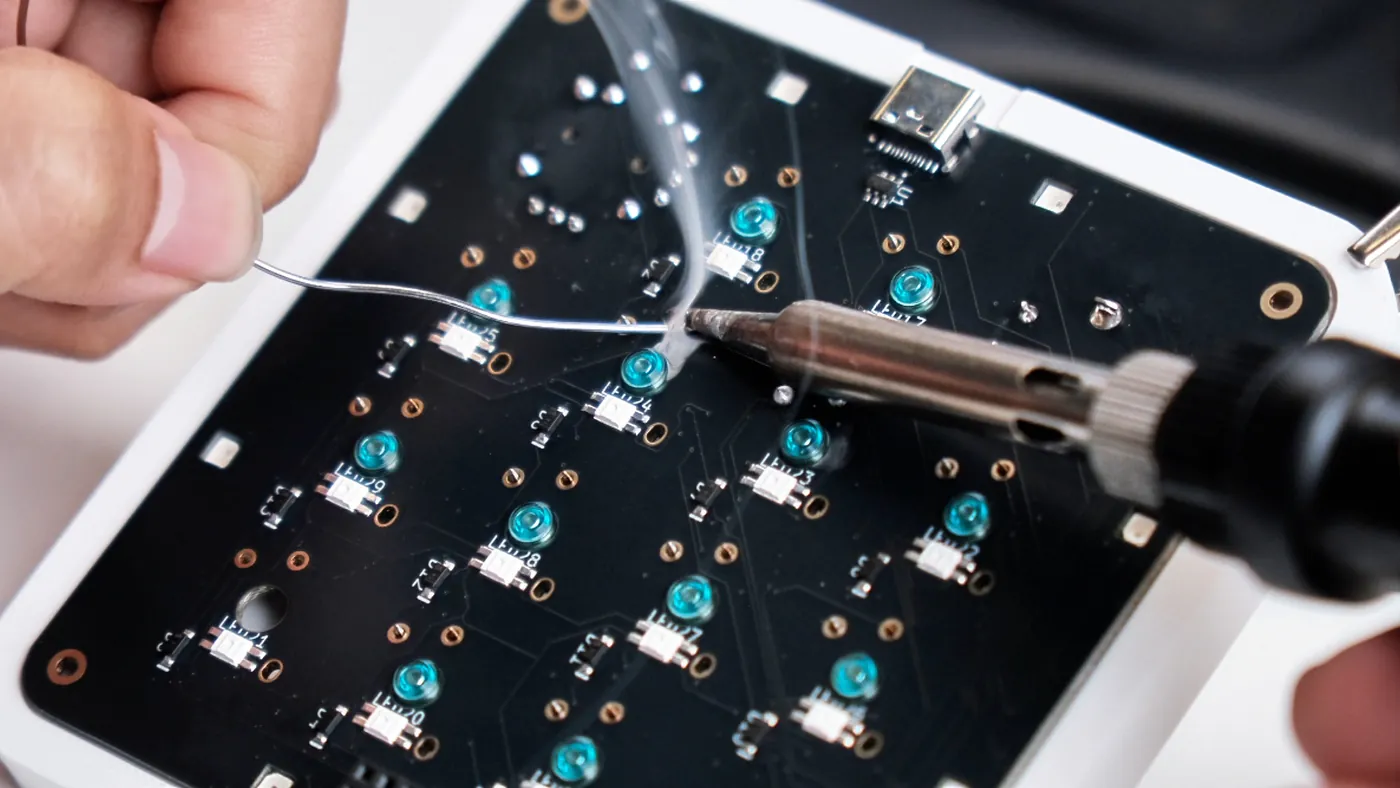
Lighting uses two WS2812-compatible chains, 21 LEDs total: 13 reverse-mount SK6812MINI-E LEDs beneath the keys, and 8 more around the perimeter as underglow. USBLC6 provides USB ESD protection, and an AP2112 regulates 3.3 V.
What one board actually costs
These are real quoted prices for a single prototype run. The SMT line is a turnkey quote: it covers the components and machine assembly, so the component detail below is nested inside it rather than added on top.
| Line | Cost |
|---|---|
| PCB (4-layer, 95 × 95 mm) | $6.93 |
| SMT assembly — turnkey, parts + placement | $18.14 |
| 13 × Kailh Choc switches | $2.97 |
| Keycap set | $8.85 |
| Total, one assembled board | $36.90 |
Inside that SMT quote, the component spend breaks down as follows — $7.67 of parts, with the rest of the line being the fab's assembly service:
| Component | Qty | Cost |
|---|---|---|
STM32F072CBT6 | 1 | $2.88 |
EC11 encoder | 1 | $1.64 |
RKJXV joystick | 1 | $0.97 |
| Passives | 1 set | $0.84 |
21 × SK6812MINI-E LEDs | 21 | $0.90 |
| 8 MHz crystal | 1 | $0.13 |
AP2112 LDO | 1 | $0.10 |
USBLC6 ESD protection | 1 | $0.05 |
| USB-C port | 1 | $0.15 |
Two things worth saying plainly about that number.
First, it is a one-off prototype quote, with hand-populated through-hole parts and no shipping, spare boards, or failed attempts included. Different fabs, finishes, and shipping choices move it; add a spare board and a courier and it climbs. My labour is priced at zero throughout.
Second — and more importantly:
$37 and $230 are not the same kind of number, and this is not a like-for-like comparison.
The commercial device runs wireless over Bluetooth, and carries the power management and cell to do it — Work Louder's equivalent Creator Micro 2 PRO lists a 2100 mAh battery. This board is wired-only: no radio, no antenna, no RF layout, no wireless stack, no charging circuit, and no radio certification. The commercial unit also arrives in a CNC aluminium and polycarbonate case; this one gets a 3D print. And the $230 buys assembly at volume, testing, packaging, distribution, warranty, support, and margin — none of which appear in a prototype quote.
The honest claim is not "six times cheaper." It is that an open board with the same control surface costs tens of dollars to make, and you can inspect and change every layer of it.
From requirements to routed copper
The workflow started with concrete requirements given to an agent: control layout, matrix, power rails, USB, LEDs, MCU resources, mechanical constraints. That conversation became CoHDL source for the schematic-level design.
CoHDL emitted the netlist, BOM, footprints, and constraints. The design then went to Quilter.ai for physical layout. The resulting boards were ordered from a fab and populated.
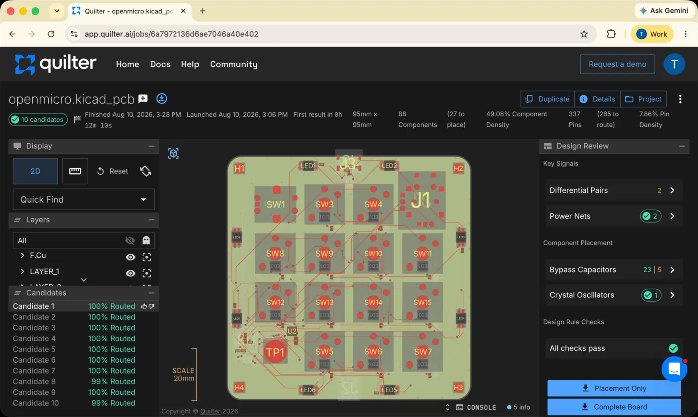
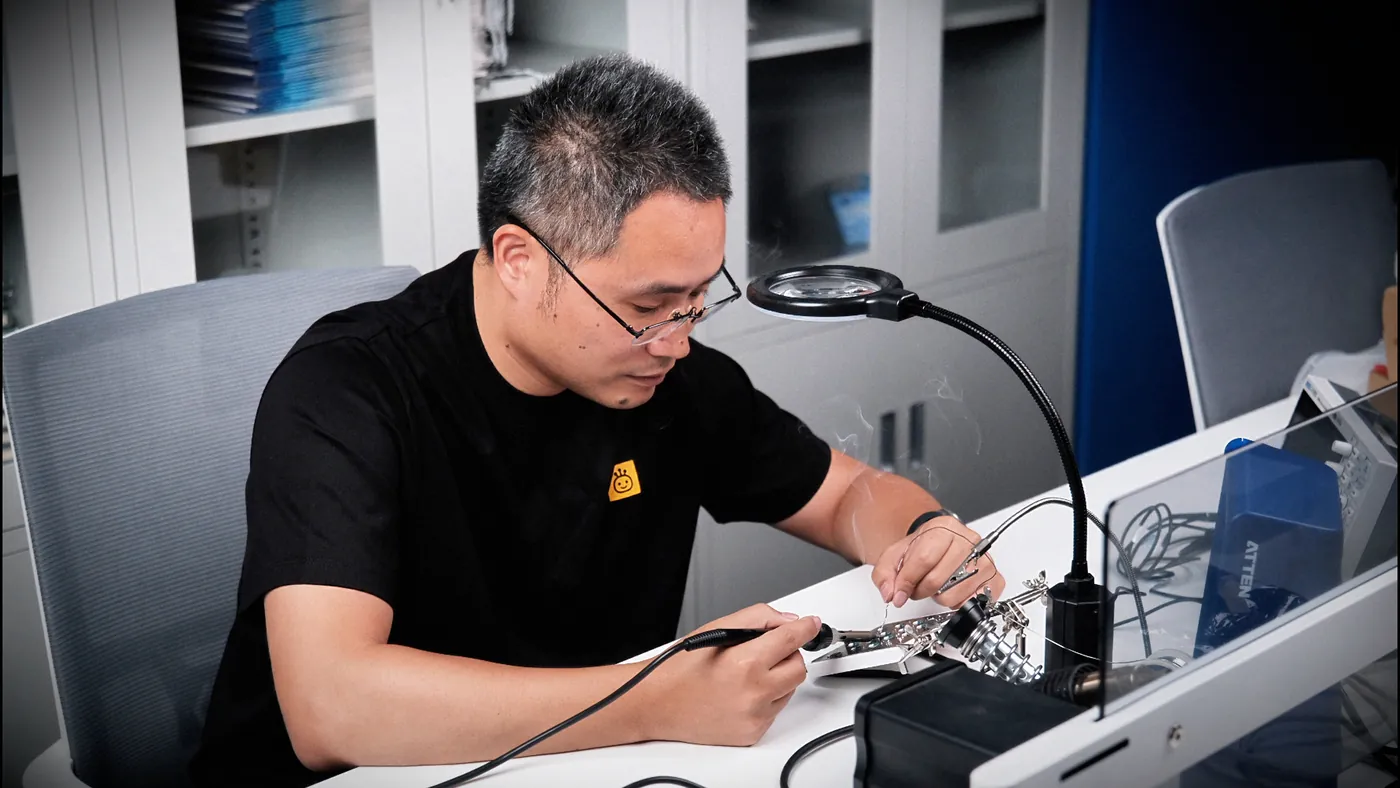
An agent also assisted with firmware and host-app development. It did not produce a finished system from one prompt. Pin assignments, component choices, generated outputs, layout, soldering, bring-up, behavior, and failure modes all required review and debugging.
The PCB is written, not drawn
The schematic for this board is not a drawing. It is source code:
inst sw: [SW_KEY; 13]
inst d: [diode::D_1N4148W; 13]

net ROW1: mcu.PA10, sw[2..=5].A
net COL1: mcu.PB5, d[0, 3, 7, 10].Cathode
Power intent can be attached to a net:
#[intent("AP2112K enable tied to VIN — always on when USB is present")]
#[high_current(500mA)]
net V3V3 [3.3V]: ldo.VOUT, mcu.VDD, mcu.VDDA, mcu.VBAT, mcu.VDDIO2, joy.X_END_B, joy.Y_END_B,
                 c_vdda.A, c_vdd_a.A, c_vdd_b.A, c_vdda_hf.A
[3.3V] is a unit annotation. #[intent(...)] makes design intent a checkable attribute rather than an unverified comment. The compiler checks units, pin-connection obligations, and power-integrity rules, then writes netlist, BOM, footprint, and constraint artifacts under hw/v1/out/. It also generates the firmware pin map from the hardware source.
Two honest boundaries. CoHDL produced the schematic and its generated outputs; Quilter.ai did the physical layout — the routing is not written. The compiler was private when this article was first published, but CoHDL is now open source. Explore the project at cohdl.org or browse the source at github.com/conol-ai/cohdl.
Part two: the enclosure
A bare PCB is not a satisfactory desktop device. It rocks on components or standoffs, exposes solder joints, and makes a side-mounted USB connector awkward to reach.
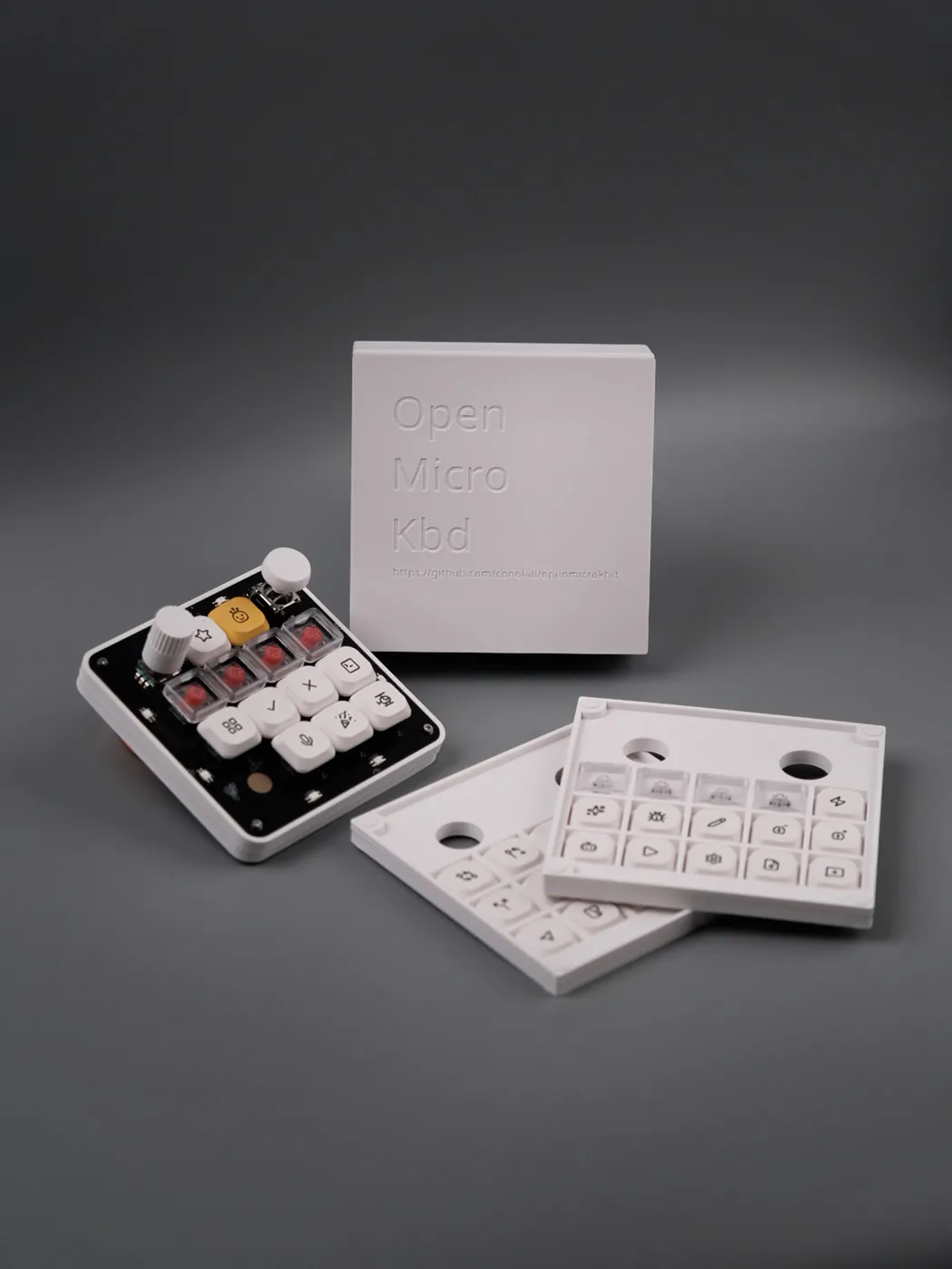
So the repository ships a printable enclosure under hw/v1/mechanical/, as both editable Fusion sources and ready-to-slice meshes: the case, the encoder knob, the joystick cap, the packaging, and the soldering jig used to hold the board while the through-hole parts go in. The board outline is there as DXF too, for anyone modelling their own.
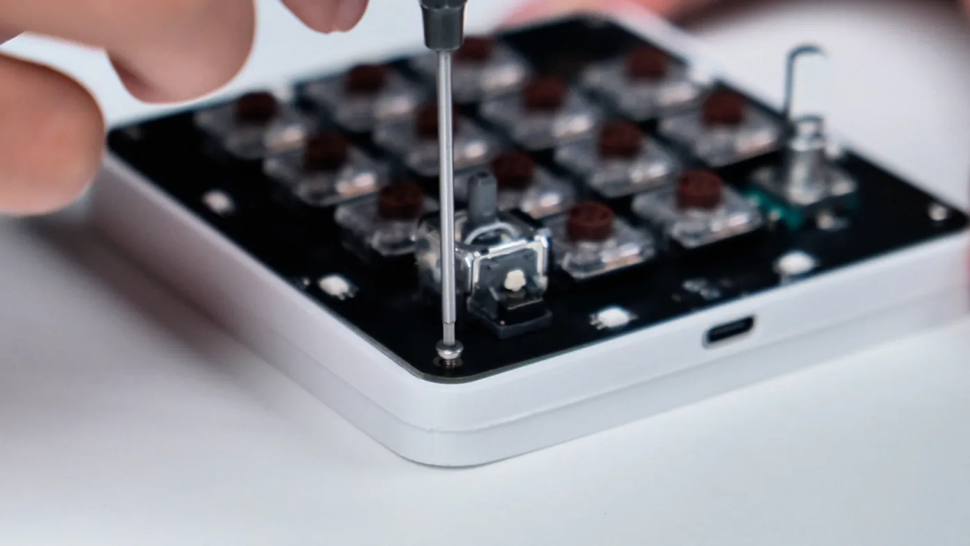
If you would rather not open a CAD file at all, the case is also published as a ready-to-print profile on MakerWorld (and on MakerWorld 中国 for anyone printing from the mainland). The profile carries the case, the knob and the joystick cap, with the soldering jig and the packaging thrown in — 0.4 mm nozzle, 0.2 mm layers, PLA or PETG, and no supports.
The enclosure is also the layer most worth remixing, and the easiest to change safely. Tilt, feet, material, encoder height, and USB-cable clearance can all vary without touching the electronics. If you design a variant, publish the editable source beside the printable output, and leave the SWD socket accessible — it is the recovery path if a firmware update goes wrong.
Part three: firmware and its failure modes
Firmware lives under fw/ and uses Rust with Embassy for thumbv6m. The current build occupies about 22 KiB of 128 KiB flash and roughly 5 KiB of 16 KiB static RAM, with LTO and opt-level="s".
There is no separate RTOS, and the crate's own unsafe is confined to a handful of narrow, commented blocks: the WS2812 inline-asm bit timing, the DFU no-init-RAM handoff into the ROM bootloader, and one memory-mapped flash read.
The COL2ROW matrix scans at 1 kHz with 5 ms debounce. The exact GPIO assignments come from the generated pin map — more on that below.
USB exposes a composite HID device — keyboard, consumer control, and a mouse interface that carries the joystick's pointer modes — plus a vendor interface on usage page 0xFF60 with 32-byte reports. bcdDevice carries the Cargo semantic version, letting the updater decide whether an update is needed without opening the vendor interface.
Deep dive one: the keymap lives on the device
Every input is a slot, and there are 24 of them: 13 keys, three for the encoder, five for the joystick, three for the touch pad. Each slot is four bytes:
pub struct Slot {
    pub kind: u8,   // none / keyboard / consumer
    pub mods: u8,   // HID modifier bitmask — ctrl, shift, alt, gui
    pub code: u16,  // keyboard usage, or consumer usage
}
That mods byte is what makes the board more than an F-key pad. A slot can emit a plain keycode, a modifier-qualified combination, or a consumer usage like play/pause. The factory defaults use F13–F20 plain and Shift+F13–F17 for the remaining five keys, so nothing collides with an existing OS shortcut out of the box — but none of that is baked in.
The whole table is persisted in the last 2 KiB flash page, at offset 0x1F800. The blob is 120 bytes in today's layout: an "OMK1" magic, a layout version, analog tuning, the 24 slots, lighting settings, and a checksum — and the loader still accepts every earlier layout version. Vendor HID commands manage it — GET_KEYMAP, SET_KEYMAP, SAVE, FACTORY_RESET.
The save path is ordered deliberately. The body is written first and the magic word is written last, as its own operation. If power dies mid-save, the header stays erased, the magic check fails on next boot, and the board comes up on factory defaults rather than a half-written keymap. The checksum catches the subtler tear where power drops between body and magic during a re-save.
Corrupt slots degrade rather than propagate: a bad kind, or a keyboard code above 0xFF, becomes a disabled slot instead of a wrong keypress.
Deep dive two: DFU without a resident bootloader
The app requests DFU with a vendor HID command. The device acknowledges it, writes a magic word into no-init RAM, and reboots.
Early startup checks and clears that marker before peripheral initialization, then jumps to STM32 ROM system memory at 0x1FFF_C800, as documented by ST AN2606.
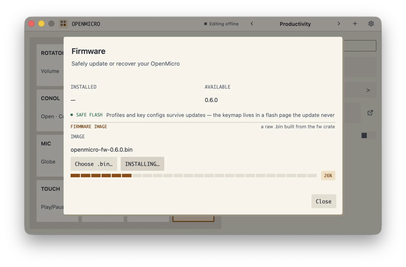
The chip re-enumerates as ST DFU device 0483:df11 on the same USB-C port, and the app speaks DfuSe (AN3156) over libusb directly: erase the covered 2 KiB pages, program in wTransferSize blocks, set the address pointer, manifest. No custom resident bootloader consumes flash, requires versioning, or has to coordinate with the application image.
Before any of that happens, the app sanity-checks the image — it validates the Cortex-M0 vector table against 128 K flash and 16 K RAM, so pointing it at the wrong .bin is refused before a single page is erased.
The failure mode still matters. BOOT0 is held low, so ROM entry is software-only. If power fails mid-programming, the application may be gone and the board will not automatically return to DFU. Recovery is the SWD socket.
That trade is acceptable for a board with an exposed debug socket. It would need reconsideration in a sealed consumer product.
Deep dive three: fitting 21 LEDs inside the USB budget
Twenty-one addressable LEDs can still exceed the USB 2.0 500 mA budget at full white. Firmware limits every channel using scaled(n / 64), across both the 13 key LEDs and the 8 perimeter LEDs sharing VBUS.
This is a static ceiling, not a dynamic current model. It neither estimates draw from the current color mix nor negotiates higher USB-C current. The worst case is predictable, but the LEDs never reach their standalone rated brightness.
The protocol is bit-banged, and its cycle counts assume a 48 MHz core. Clock configuration is therefore part of driver correctness, not merely performance tuning.
Deep dive four: USB disciplines the core clock
Although the board includes an 8 MHz HSE crystal, the current firmware does not depend on it. HSI48 drives the CPU and USB peripheral at 48 MHz.
The STM32 Clock Recovery System disciplines HSI48 against USB Start-of-Frame packets. USB becomes the timing reference, keeping the core at the frequency the LED driver assumes while leaving the crystal available for future firmware and debugging.
The boundary is explicit: this design assumes a USB-connected device. It would be a poor clock strategy for a wireless, battery-powered variant running for long periods without SOF packets — one concrete example of how far the two designs diverge once a radio is involved.
Deep dive five: the pin map is generated, not copied
Firmware does not choose its pins independently. CoHDL generates the pin map from the hardware source.
That removes a common two-file failure: changing a schematic pin while forgetting the corresponding firmware constant. Generated files are not automatically correct; they preserve bad choices as reliably as good ones. The narrower benefit still holds — electrical intent and firmware assumptions cannot silently drift apart.
Part four: the companion app
The Rust and GPUI app under app/ does three things.
It finds the pad over the vendor HID interface (1209:0001, usage page 0xFF60) and shows live connection state, the running firmware version via an in-band query, and the serial.
It updates firmware over the DFU path described above — pick a .bin, press Install, and it validates, reboots to ROM DFU, programs, waits for re-enumeration, and confirms the new version.
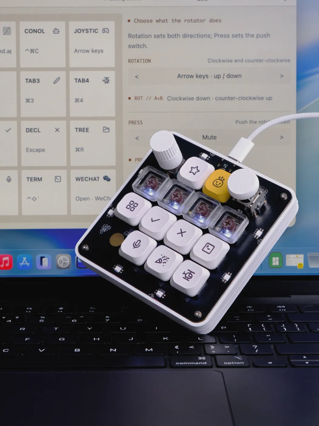
And it edits the keymap, reading the current table off the device, letting you reassign any slot, and writing it back into flash. Because the mapping lives on the board, it travels with the hardware: configure it once, plug it into a different machine, and the keys behave the same with no software installed there.
Separately, the app can bind a key to a host-side action — running a shell command (sh -c, or cmd /C on Windows) or opening a URL, file, or app through the OS default handler. Those bindings are host-side by nature and live in the app's own configuration; a keyboard cannot launch your build script by itself. So there are two layers available, and the trade-off between them is explicit: device-resident keymaps are portable, host-side actions are more powerful.
Scope, and what you are choosing
A different device with different priorities, not a feature-for-feature substitute:
- Wired only — USB-C, with no radio and no battery. The commercial device works wirelessly over Bluetooth.
- Printed case, not machined — the enclosure is FDM plastic rather than CNC aluminium and polycarbonate, though the source is yours to change.
- Rust and Embassy instead of QMK/ZMK — a small async firmware with direct control over USB, updating, keymap persistence, and peripherals, in exchange for the tooling ecosystem those projects have built. It is not VIA-compatible; keymap editing goes through this project's own app.
- No Codex integration — no ChatGPT desktop bridge and no agent-status choreography. The vendor HID interface is open and documented in the firmware source for anyone who wants to build one.
The commercial product arrives assembled, enclosed, tested, and supported. This project asks you to supply assembly and time, in exchange for a board you can modify.
Build one
The repository is github.com/conol-ai/openmicrokbd:
- CoHDL schematic source —
hw/v1/src/ - Generated netlist, BOM, footprints, constraints —
hw/v1/out/ - The routed board —
hw/v1/pcb/openmicro.kicad_pcb, opens in KiCad 10+ - Fab-ready manufacturing package —
hw/v1/fab/ - Printable enclosure, knob, joystick cap, packaging, soldering jig, and the board outline DXF —
hw/v1/mechanical/, or straight off MakerWorld (中国站) - Datasheets for every active, connector, and electromechanical part —
hw/v1/docs/ - Firmware —
fw/ - Companion app —
app/
Prebuilt, notarized macOS builds of the companion app ship with every GitHub release, alongside the firmware binaries. Or build both from source:
git clone https://github.com/conol-ai/openmicrokbd
cd openmicrokbd
scripts/build-firmware.sh dist        # production binary + debug ELF
cd app && cargo run --release --locked
To order boards, upload hw/v1/fab/openmicro-gerbers.zip with the assembly BOM and the SMT placement CSV. The board is 4-layer, 95 × 95 mm, 1.6 mm FR-4; DRC reports zero unconnected items, and the remaining clearance and silkscreen flags are documented and accepted in hw/v1/fab/README.md. Two ordering notes that matter: specify ENIG so the capacitive touch pad works properly, and note that the through-hole parts — switches, encoder, joystick — are hand-populated, since the pick-and-place file covers SMD only.
If you build one, keep the SWD socket reachable. Because BOOT0 is held low, that socket is the recovery path after a power loss during a firmware update.
The manufacturing files are in the repository. The point was never to show you a board — it was to let you make one.
Thanks to Quilter.ai for the physical layout, and to the readers who challenged the original product's closed feedback path. The useful criticism was never that a macropad is silly. It was that a general-purpose input device should stay general-purpose.
One last thing, for anyone who scrolled past the code. That schematic was never drawn in an editor — it was written, type-checked, and compiled. The language is called CoHDL, and it is the part of this project I am most interested in. CoHDL is now open source; browse the compiler and libraries at github.com/conol-ai/cohdl. The generated files in hw/v1/out/ remain a concrete record of what it produced for this board.
The keyboard made the argument; now the language is open too. The PCB is written, not drawn — and you can read every line of both today.